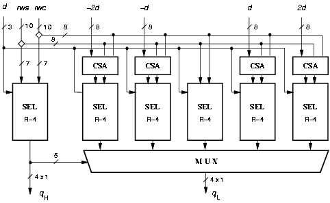
Figure 4.17: Selection function for radix-16.
The radix-16 division algorithm is implemented by the residual recurrence
|
| (20) |
The radix-16 division unit is obtained by overlapping the computation of two radix-4 digits [30]. Consequently, the quotient digit is split into two parts qH and qL such that qj = 4qH + qL with digit set {-2,-1,0,1,2} in each part, resulting in the digit-set [-10,10] for qj (a = 10). The quotient digit is determined, at each iteration, by the selection function depicted in Figure 4.17. Once the digit qH is chosen, its value is used to select among all the possible combinations of qH d. The redundancy factor is r = [a/(r-1)] = [2/3]. The residual w[j] is stored in carry-save representation (wS and wC). The signed-digit representation of the quotient is converted to conventional two's complement representation and rounded by the on-the-fly convert-and-round unit.

Figure 4.17: Selection function for radix-16.
The implementation of the standard divider, optimized for shortest latency, is shown in Figure 4.18. Table 4.6 shows the delay through the two parts of SEL. Note that the larger delay of SELqL is compensated by the additional carry-save adder in the recurrence (Figure 4.18) in the path from SELqH.
The critical path post-layout is 9.2 ns and 16 cycles are required to complete the operation, corresponding to a latency of 150 ns. The energy dissipated by this basic implementation is Ediv = 46.0 nJ and the contributions of the blocks is shown in Table 4.9 in column ßtandard".
| path | delay [ns] | ||
| qL | SELqL - MULT - HA - REG | ||
| 5.7 + 1.4 + 0.6 + 1.5 | = | 9.2 | |
| qH | SELqH - MULT - HA - FA - REG | ||
| 4.0 + 1.4 + 0.6 + 1.1 + 1.5 | = | 8.6 | |
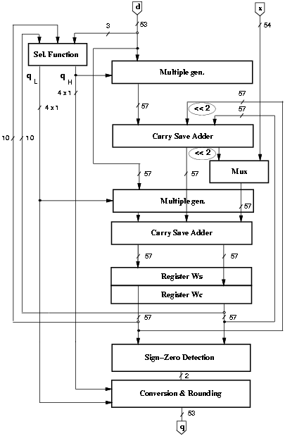
Figure 4.18: Basic implementation radix-16.
The retiming of the recurrence is done by moving the selection function from the first part of the cycle to the last part of the previous cycle. Two 4-bit registers are needed to store the quotient digit. After the retiming the critical path is limited to the 10 most-significant bits of the recurrence. As shown in Figure 4.19, in order not to increase the cycle delay in the retimed unit, the clock of register qL is skewed.
Since in the retimed implementation the selection function is placed after the second CSA, instead of directly after the registers, there is a large increase in the number of glitches, which are responsible for the increased dissipation of the selection function. One way to filter those glitches is to buffer the selection function with multiplexers acting as latches, as described in Figure 3.13 at page pageref. The select signal is driven by a different clock (same period, different phase) that enables the muxes to transmit the value from the CSA when it is stable, and hold the current value otherwise. However, in this case the delay of the mux affects the critical path. For radix-16 the energy dissipated in the selection function is halved, but the critical path is increased by about 5%. For this reason, the value is not included in Table 4.9.
For the 44 least-significant bits the radix-2 CSA is replaced by a radix-16 CSA (R16 CSA) that for each digit of the radix stores only one carry bit. Figure 4.20 shows the radix-16 CSA and Table 4.7 explains how the two level of adders are connected to produce the correct residual. The number of flip-flops in register Wc is reduced from 57 to 25.
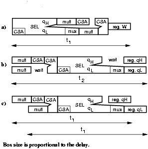
Figure 4.19: Retiming and critical path.
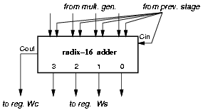
Figure 4.20: Radix-16 CSA.
| iter. j | iteration j+1 | ||||||||||
| first level | second level | ||||||||||
|
| |||||||||||
|
ws0 | 0 maS | ma0 | S0 | 0 | mbS | mb0 | ws0 | ||||
| ws1 | 0 | ma1 | S1 | 0 | mb1 | ws1 | |||||
|
ws2 | wc2 | 4ws0 | ma2 | S2 | 4S0 | mb2 | ws2 | wc2 | |||
| ws3 | 4ws1 | ma3 | S3 | 4S1 | mb3 | ws3 | |||||
|
ws4 | 4ws2 | 4wc2 | ma4 | S4 | C4 | 4S2 | mb4 | ws4 | |||
| ws5 | 4ws3 | ma5 | S5 | 4S3 | mb5 | ws5 | |||||
|
ws6 | wc6 | 4ws4 | ma6 | S6 | 4S4 | 4C4 | mb6 | ws6 | wc6 | ||
| ws7 | 4ws5 | ma7 | S7 | 4S5 | mb7 | ws7 | |||||
|
ws8 | 4ws6 | 4wc6 | ma8 | S8 | C8 | 4S6 | mb8 | ws8 | |||
| ws9 | 4ws7 | ma9 | S9 | 4S7 | mb9 | ws9 | |||||
|
ws10 | wc10 | 4ws8 | ma10 | S10 | 4S8 | 4C8 | mb10 | ws10 | wc10 | ||
| ws11 | 4ws9 | ma11 | S11 | 4S9 | mb11 | ws11 | |||||
| ...... | ...... | ...... | |||||||||
In order not to increase the cycle time when using radix-16 CSA the two paths shown in Table 4.8 should have the same delay. Therefore, the condition to be satisfied is:
|
|
| MSBs: | MULT | HA | SEL QL | REG |
| LSBs: | MULT | R16 CSA | R16 CSA | REG |
Furthermore, the 7 most-significant bits assimilated in the selection function could be stored in the register Ws, saving 7 additional flip-flops. However, in the radix-16 case, the assimilated value must be selected among the 5 possible alternatives (see Figure 4.17) and this requires an additional multiplexer driven by qH that increases the load both on qH and qL. For this reason the 7 MSBs bits are stored in carry-save representation.
In the original on-the-fly conversion and rounding algorithm the partial quotient is stored in two registers (Q and QM). By implementing the modified algorithm, with r = [2/3], only register Q (54 bits) and register C (14 bits) are needed. With the implementation of the modified algorithm the number of flip-flops in the convert-and-round unit is reduced from 108 to 69 and the power dissipated from 10.7nJ to 2.4nJ, resulting in a reduction of about 20% in the whole divider.
When applying dual voltage to the recurrence, the two cases with a radix-2 and a radix-16 CSA must be considered. As explained in Section 3.6, the time slack is longer for the radix-2 CSA implementation and the possible voltage V2 is lower. In particular, for the radix-16 divider (critical path is 9.2 ns), we get the following values:
The values of Ediv indicated above take into account both the different number of flip-flops in register Wc and the voltage scaling in the convert-and-round unit.
It is clear that the implementation with radix-2 CSA is the most convenient for dual voltage.
The synthesized selection function showed a delay of 4.0 ns through qL, and 3.0 ns through qH with delay constraints met. In addition the reduction in energy dissipation, obtained by incremental compilation with power dissipation constraints resulted to be about 25%.
Table 4.9 reports the average energy dissipation and area for the standard and the low-power implementation, which is shown in Figure 4.21.
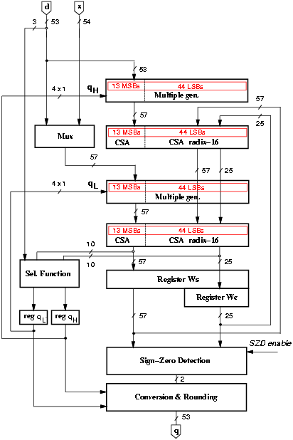
Figure 4.21: Low-power radix-16 divider.
| standard | low-power | synopsys | dual voltage | synopsys | |
| blocks | nJ | nJ | (est.) nJ | (est.) nJ | (est.) nJ |
|
control | 0.5 | 0.5 | 0.5 | ||
| clk tree | 0.5 | 0.5 | 0.5 | ||
|
mux | 2.6 | 0.4 | 0.4 | ||
| mul. gen. H | 2.5 | 1.6 | 0.8 | ||
| CSA H | 3.3 | 3.3 | 1.9 | ||
| mul. gen. L | 2.7 | 1.8 | 1.0 | ||
| CSA L | 5.0 | 4.3 | 2.5 | ||
| sel. func. | 5.9 | 8.2 | 6.1 | 8.2 | 6.1 |
| register Ws | 4.4 | 4.3 | *2.1 | ||
| register Wc | 4.2 | 1.6 | *1.9 | ||
| register qH | - | 0.2 | 0.2 | ||
| register qL | - | 0.2 | 0.2 | ||
|
SZD | 3.7 | 0.6 | 0.6 | ||
| C&R unit | 10.7 | 2.4 | *0.9 | ||
|
Ediv [nJ] | 46.0 | 30.0 | 28.0 | 22.0 | 20.0 |
| Ratio | 1.00 | 0.65 | 0.60 | 0.50 | 0.45 |
|
Area [mm2] | 2.2 | 1.8 | - | - | - |
| Values marked * include level shifters. | |||||
Figure 4.22 shows the breakdown, as a percentage of the total, of the energy dissipated in the main blocks composing the unit.
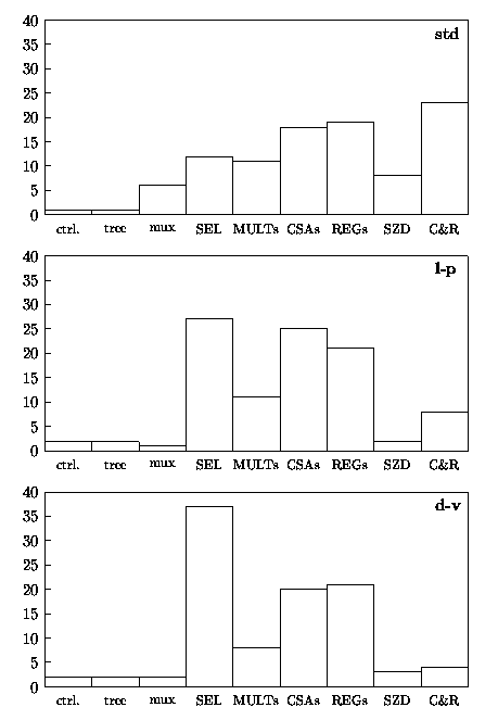
Figure 4.22: Percentage of energy dissipation in radix-16 divider.
In the std the largest part of energy is dissipated in the convert-and-round unit (about 25%). With the application of the energy reduction techniques, the energy dissipated in C&R unit is reduced to less than 10% of the total for l-p and less than 5% for d-v. On the other hand the contribution of the selection function to the total energy dissipation increases up to 35% of the total in d-v. By optimizing the selection function with Synopsys Power Compiler, a reduction of 25% in the block would reflect in a contribution of about 30% of the total in d-v.